Flasher Circuit using NE 555
Description
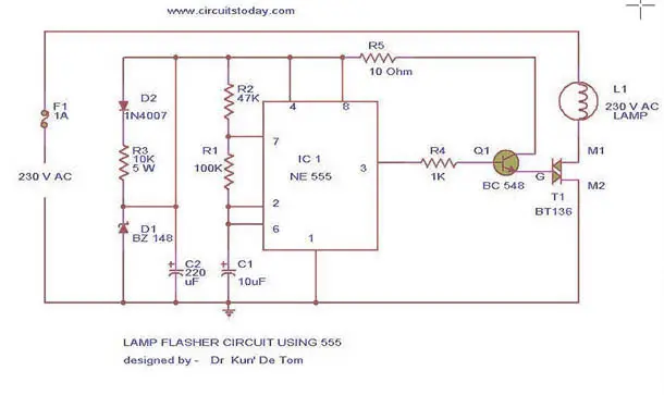
This is the circuit diagram of lamp flasher operated from mains. By this you can flash up to 200 Watt lamps at rates determined by you. IC NE555
is wired as an astable multivibrator for producing the pulses for
flashing the lamp. The flashing rate can be set by the value of
resistors R2 & R3.
Diodes D1 & D2 provides a half wave rectified regulated supply
for the IC. Transistor T1 is used to drive triac and triac BT136 for
driving the load. Resistor R4 limits the base current of Q1.
Flashing Circuit Diagram & Parts List
Notes
- Assemble the circuit on a good quality PCB or common board.
- Connect a 100K pot instead of R2 if you need frequent changes in rate.
- Many parts of the circuit are live with potential shock hazards.So please be careful.
- As usual use an IC holder for mounting the IC.

Wonderful idea. Just what I need for my science project to drive an electromagnet (paired with potentiometer to jiggle small permanent button magnet to demonstrate variable intensity and frequency). But how can I run this circuit on 24 VAC circuit? Please tell what resistors to use? change to what ohm? to run on a 24 VAC circuit?
ReplyDelete